Inverter Filter Circuit Diagram
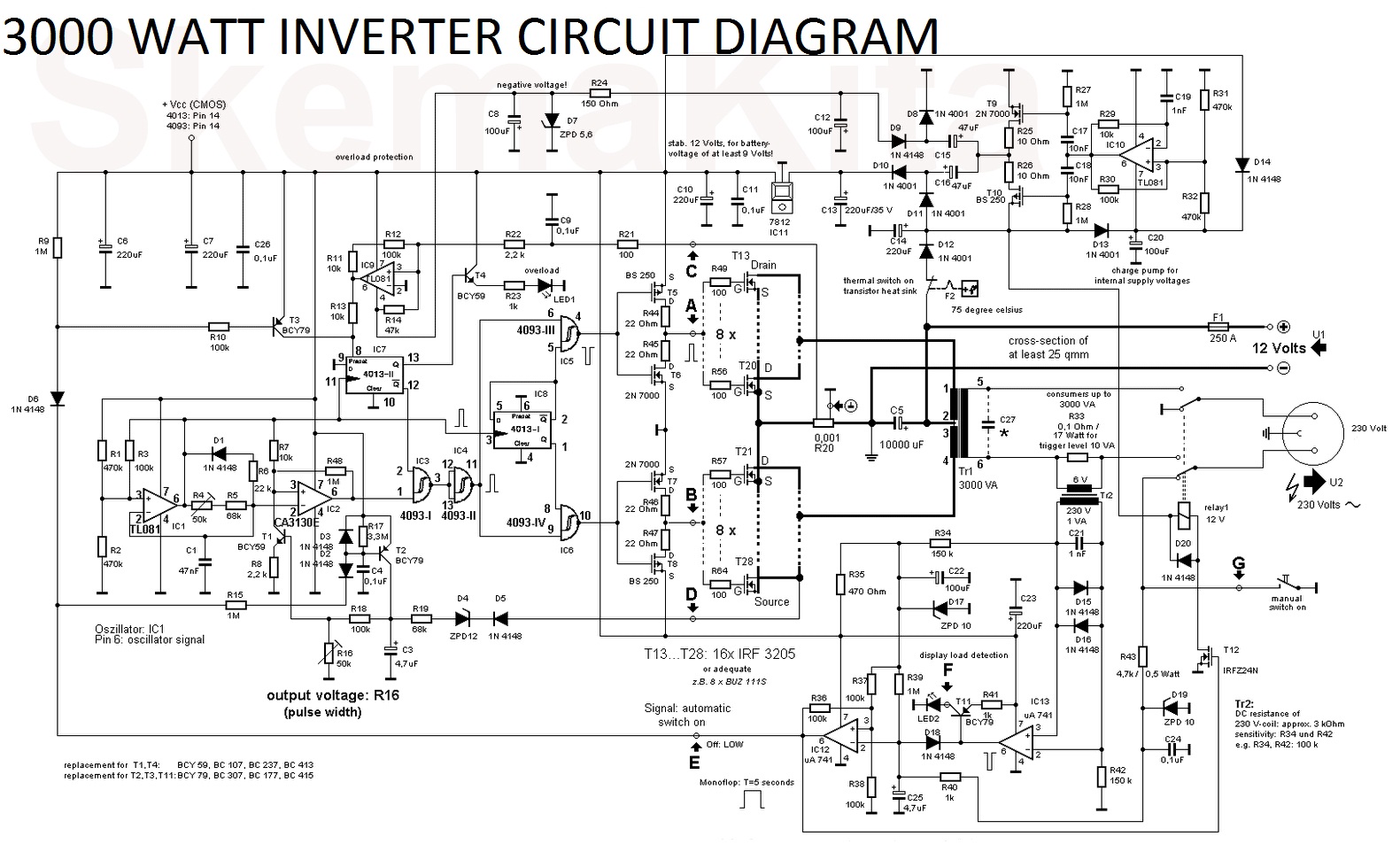
Inverter diagram circuit watt 3000 3000w pcb vac vdc electronic skema layout here Interlocking gate drivers for improving the robustness of three-phase Lc analog
Onan 4000 Rv Wiring, Onan, Free Engine Image For User Manual Download
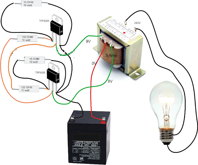
Mosfet inverter irfz44 make only Onan 4000 rv wiring, onan, free engine image for user manual download 12v dc to 220v ac inverter circuit & pcb
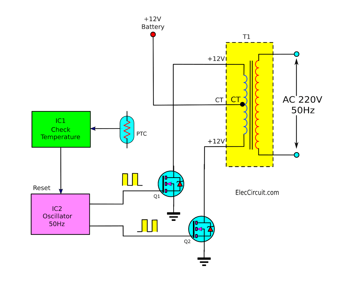
Operation of 200w inverter circuit diagram
Scheme of a conventional inverter output power filter.Inverter : lcr filter(output side making filter) : hitachi industrial 3000 watt inverter circuit diagramModular ac line emi filters explained – passive components blog.
Conventional inverterMake a simple low cost 100w inverter (12v dc to 220v ac) ~ learneverythings Emi noise capacitor typical differential inductor cx capacitors passive converters reduce attenuate edn selecting contributesInverter rangkaian components phone circuits sederhana pilas baterias diagrama circuito decent.

Filter circuit inverter diagram
Figure 2-3. inverter emi filter schematic diagram.Filter circuit for inverter Inverter tm static circuit emi filter tm11 continued description manualDiagram block inverter watt 200watt inverters circuit mosfet operation 50hz output circuits oscillator electronic control 200w eleccircuit projects high figure.
Phase three gate inverter inverters isolated drivers ti industrial vfd robustness interlocking improving schematic 3phase figure technicalInverter circuit ship filter forces armed naval turkish given Inverter circuit 12v circuits 230v coupledSelf oscillating inverter with irfz44 mosfet only, no ic needed!.

Lc filter
Simple inverter circuit diagramLcr filter inverter connecting diagram hitachi output making side 75kw model Schematic of the inverter with active filter7 simple inverter circuits you can build at home.
12v 220v how2electronicsInverter 100w simple 12v 220v dc ac circuit mosfet cost low make cd4047 irf540 ic using .


