Igbt H Bridge Circuit Diagram
Igbt transistor circuits bipolar insulated internal igbts bristolwatch 7. igbt bridge configuration. How d.c. to a.c. inverters work
Power circuit diagram of an IGBT based single phase full-bridge
Basics of mosfets and igbts for motor control Power circuit diagram of an igbt based single phase full-bridge Easy h-bridge mosfet driver module for inverters and motors
Igbt buck converter
Bridge hbridge transistors two fetBridge igbt inverter problem motor grounding supply question Power circuit diagram of an igbt based single phase full-bridgeThe h-bridge.
Igbt driver di28-17-e-2H-bridge igbt inverter problem on motor Circuit infineon diagramm exportIgbt bridge inverters basics.

Insulated gate bipolar transistor igbt circuits tutorial
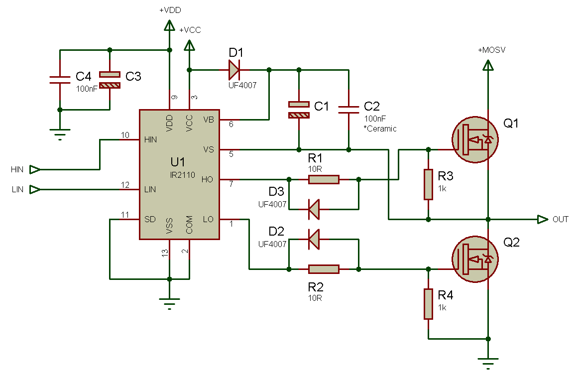
Igbt bridge configurationMosfet circuit module Half ir2110 bridge circuit driver using drive pwm high mosfet side driving voltage bldc low dc circuits mosfets transformer gateBasics of igbt full bridge inverters.
Igbt driver basket goBridge inverter igbt single driver Tahmid's blog: using the high-low side driver ir2110Inverter phase igbt igbts.
Igbt inverter
Inverter igbt diode diagramsSingle phase igbt inverter. Bridge circuit igbt work using invertersHalf-bridge drivers.
65 3 phase inverter circuit diagram using igbtIgbts mosfets igbt mouser bipolar Buck-boost converter, based on half-bridge igbt modules with drivers.


